
BS EN 60034-8 gives motor winding configurations and terminal identifiers, in this article and on the associated drawings the term terminal idents is used in place of terminal identifiers and means the same.
The standard also determines the motors rotation when connected to the power supply. Thus if a switchboard or motor control centre phase rotation is known, which it should be, and that phase rotation is for phases L1, L2 & L3 to peak in that order, for some reason this is stated as being clockwise rotation even though the vectors are travelling in an anti-clockwise direction. If the vectors are fixed then the observer rotates around the vectors in a clockwise direction for the phases to peak in the correct order.
Some engineers especially ones that sit on standards committees have brains similar to those of politicians although it would be expected that engineers would have a superior intellect to that of politicians!!!
So that there is a proper reference for the electricity supply, phase L1 (red phase in olde English, brown phase in European) should be designated as the site reference phase.
From the above a motors rotation can be set at the design stage. It should therefore never be necessary to alter the cable terminations to a motor to effect a change of rotation during the testing and commissioning stage of a project; to do so should be considered a design failure as well as being an unnecessary expenditure of time, effort and money to make the correction.
On a particular project which had almost one hundred and seventy motors the mechanical contractor was obliged to provide a motor list and include on that list the direction of rotation of each motor, analysis of the list showed that for two thirds of the motors the normal direction of rotation was anti-clockwise. During the commissioning phase of that project not one motor had to have its direction of rotation corrected.
Nearly all sites are connected for a clockwise phase rotation. Most electricians will unless instructed otherwise always connect L1 to U, L2 to V and L3 to W, this is why motors nearly always run the wrong way when first connected. If you dont know the required rotation of a motor then connect for anti-clockwise rotation as statistically there is a greater chance of that being correct.
In its simplest form a three phase motor will have three windings and three terminals the windings will be connected internally in either a star or delta configuration. British and IEC standards give each winding a letter designation U, V and W. If the phase rotation is as described above then connecting L1 to U, L2 to V and L3 to W will result in the motor running in a clockwise direction when looking back towards the drive shaft.

As motors increase in output it is normal to bring out each winding to individual terminals the windings are again identified with letters, the start and finish of each winding is identified by the numerals 1 and 2 respectively. Thus the terminals for each winding are U1 and U2, V1 and V2, and W1 and W2. These motors will likely have a dual voltage rating 400V when connected in delta and 690V when connected in star. For use in England and the rest of the European Union it is the 400V delta rating that is important as the motor can be used in conjunction with star/delta starters

It should be noted that the actual winding connections for clockwise and anti-clockwise rotation change. Although for direct on line, Korndorffer and rotor resistance starting changing phases L1 and L2 will effect a directional change, using that method when star delta starting is employed will cause a large current spike during the star to delta change-over in one direction of rotation, that current spike can be as high as 167% of the current spike when the correct connections are used. To minimise that current spike it is necessary to use a second delta contactor in reversing star delta starters.
The current spike due to incorrect connection can be shown from an examination of the vector diagrams below

During the switch-over phase when the star contactor is open and the delta contactor has not closed the rotor lags behind the rotating field. Its magnetic field induces a decreasing residual voltage as indicated in the above vector diagram by the vector UL1-N. When the delta contactor energises the stator winding carrying the residual voltage is connected to the line voltage UL1-L3 which is nearly in equilibrium as can be seen by the length of vector ΔU. Consequentially the current surge resulting from this voltage will be low.

When the windings are incorrectly connected then during the open circuit period between the star contactor opening and the delta contactor closing the rotor again lags behind the magnetic field which induces a reducing residual voltage as shown by vector UL1-N. When the delta contactor energises that residual voltage is connected to the line voltage UL1-L3 which has a different vectorial direction thus the resultant voltage as indicated by vector ΔU is significantly higher than when the correct connections are used this results in a correspondingly higher current surge.
The rate of decrease of the residual voltage in the stator is dependant on the motor design and the motor plus driven load inertia; the time taken between the star contactor opening and delta contactor closing is dependant on the operating time of the contactors, their mechanical interlock reset time and any time introduced by the star delta change-over timer. It is not possible to determine a general rule for the optimum time delay between the two contactors operating, it requires individual calculation using data most motor manufacturers are reluctant to divulge, and as for the getting the relevant data from the mechanical engineers there is more chance of a politician telling the truth, far better and quicker to connect the motor correctly in the first place.
The motor windings described above will result in single speed motors, the speed will depend on the number of poles that a motor has and the supply frequency. The load will of course affect the speed however it is normal to state the nominal speed which is defined using the formula:-
Nrpm = supply frequency x 60 / number of pairs of poles
It is normal to state the total number of poles when describing a machine thus it is necessary to divide that total by two to determine the number of pairs of poles.
For example a four pole machine connected to a 50Hz supply will have two pairs of poles and a nominal speed of 1500rpm, which is probably the most widely used, other standard speeds for 50Hz supplies are for two pole 3000rpm, six pole 1000rpm, eight pole 750rpm, ten pole 600rpm and twelve pole 500rpm. For 60Hz supplies this equates to 3600,1200, 900, 720 and 600 respectively.
Motors are also manufactured with two or more windings with each having a different number of poles which gives two or more speeds, there is also a winding configuration called a Dahlander winding, sometimes known as a tapped winding, which by changing the winding configuration changes the number of poles by a factor of two. Then there is a combination of a Dahlander and separate winding to give three speeds, the separate winding can provide the low, intermediate or high speed and the Dahlander the other two speeds. There are even motors with double Dahlander windings which gives a total of four speeds.
The windings and terminal idents of these various motors are shown below:-
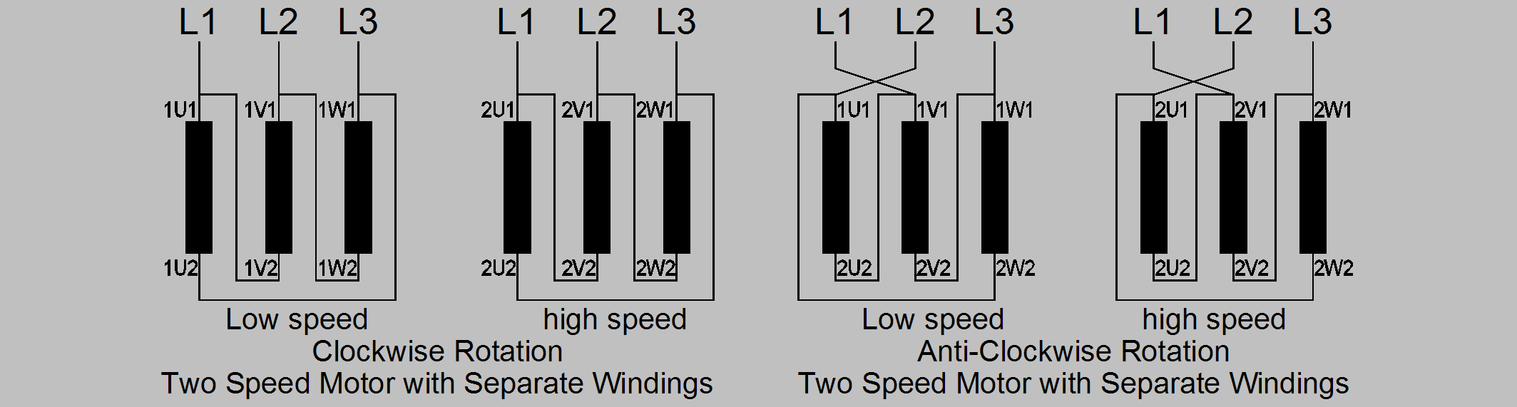
Details of terminal idents for two speed motors with two separate windings.
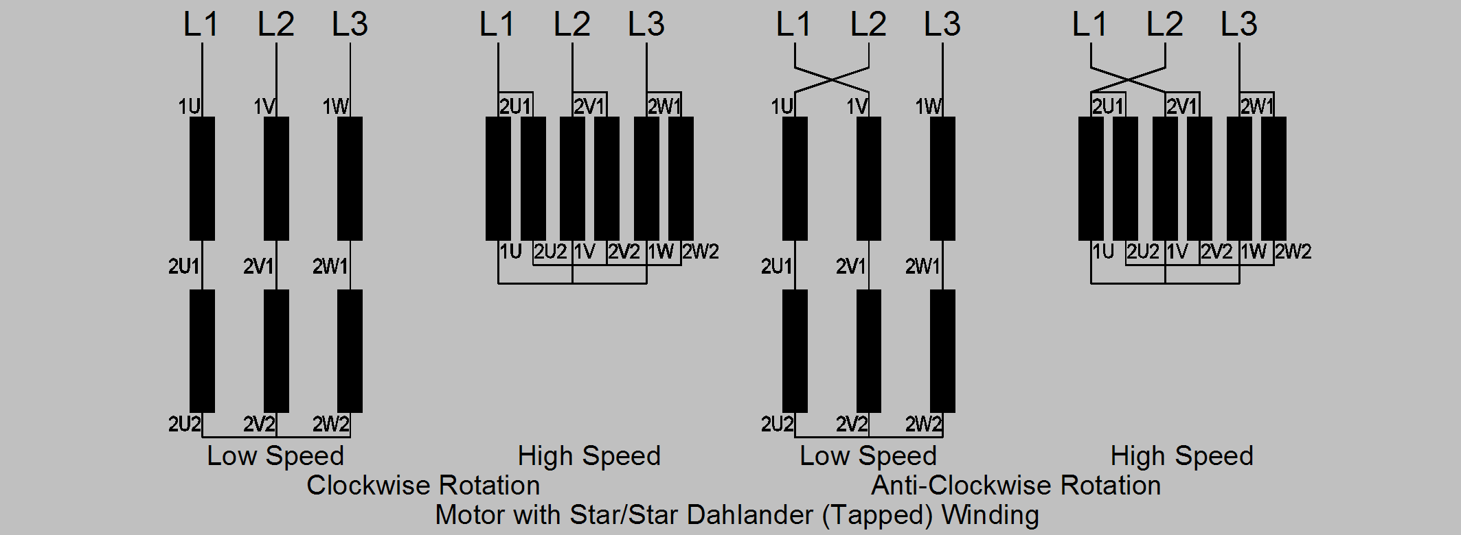
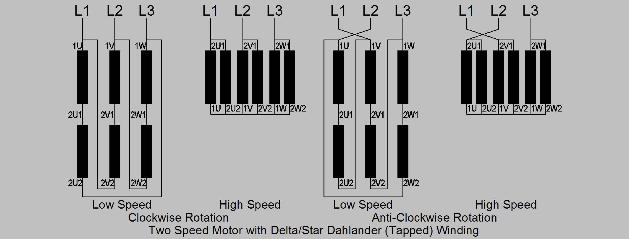
The Dahlander or tapped windings can be either star or delta connected for the low speed winding and parallel star for the high speed winding. For constant torque the low speed windings are connected in delta, for fan drives and other machines where greater torque is required for the higher speed the windings are connected in series star for low speed and parallel star for high speed.
Details of terminal idents for two speed motors with Dahlander star/double star windings.
Details of terminal idents for two speed motors with Dahlander delta/star windings.
Details of terminal idents for three speed motors with Dahlander star/star windings for intermediate and high speed and a separate winding for low speed (clockwise rotation).
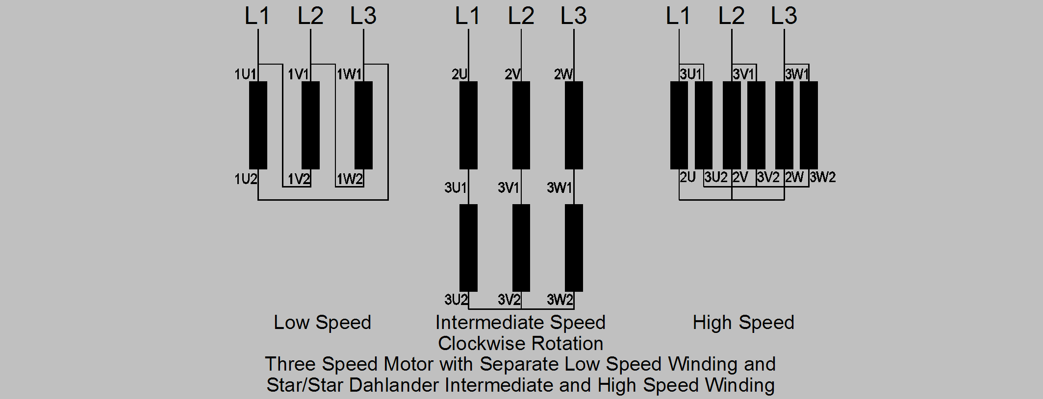
This combination of windings is useful as the low speed winding can be used for assisted starting that is star delta or Korndorffer starting to minimise the starting current.
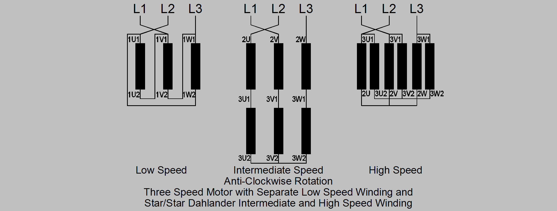
Details of terminal idents for three speed motors with Dahlander star/star windings for intermediate and high speed and a separate winding for low speed (anti-clockwise rotation).
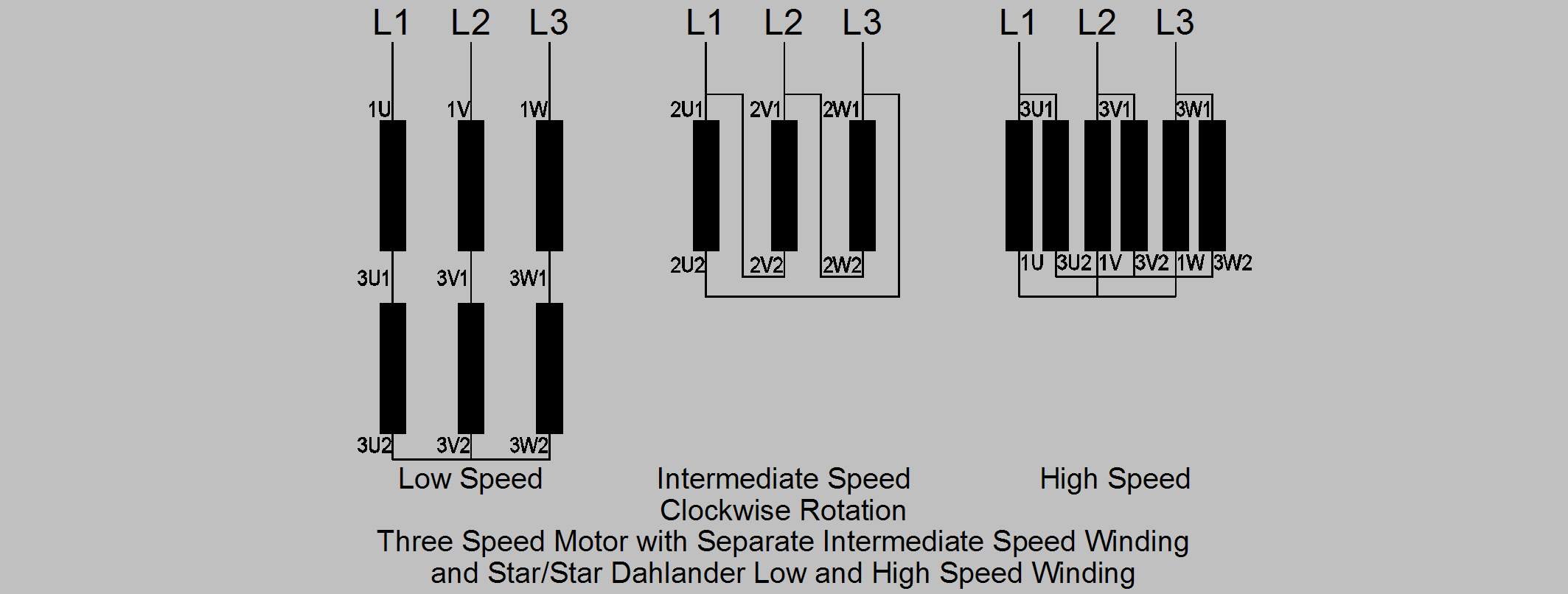
Details of terminal idents for three speed motors with Dahlander star/star windings for low and high speed and a separate winding for intermediate speed (clockwise rotation).
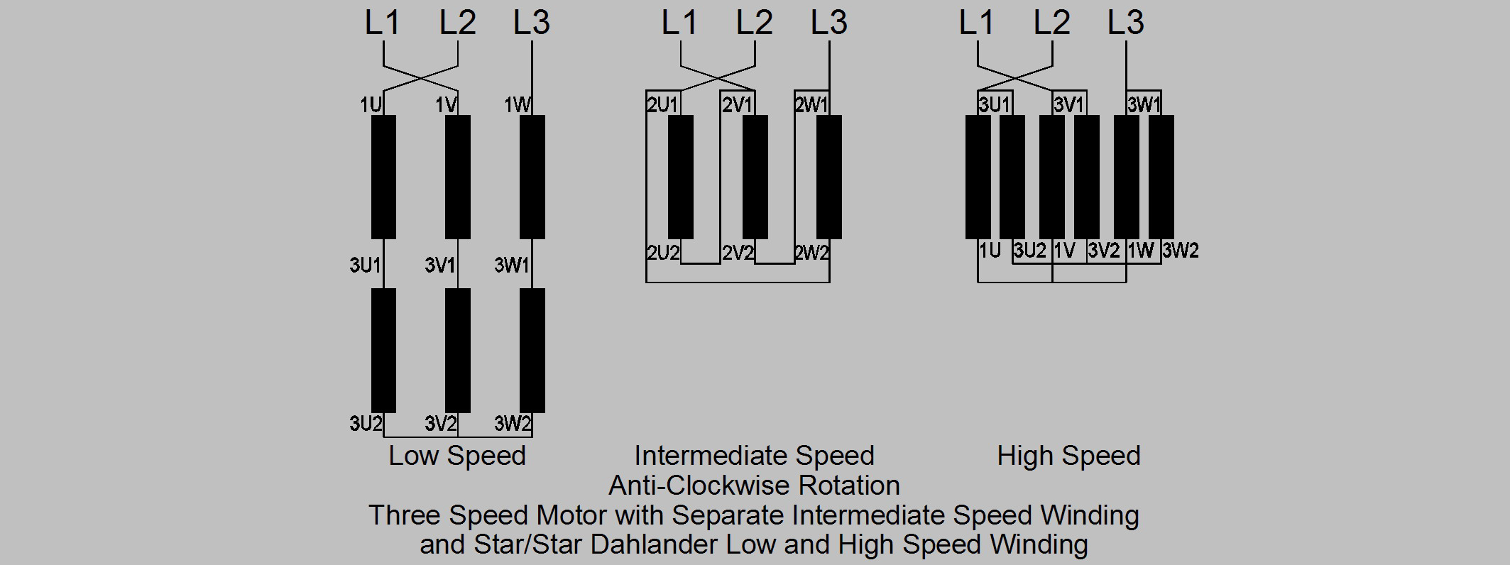
Details of terminal idents for three speed motors with Dahlander star/star windings for low and high speed and a separate winding for intermediate speed (anti-clockwise rotation).
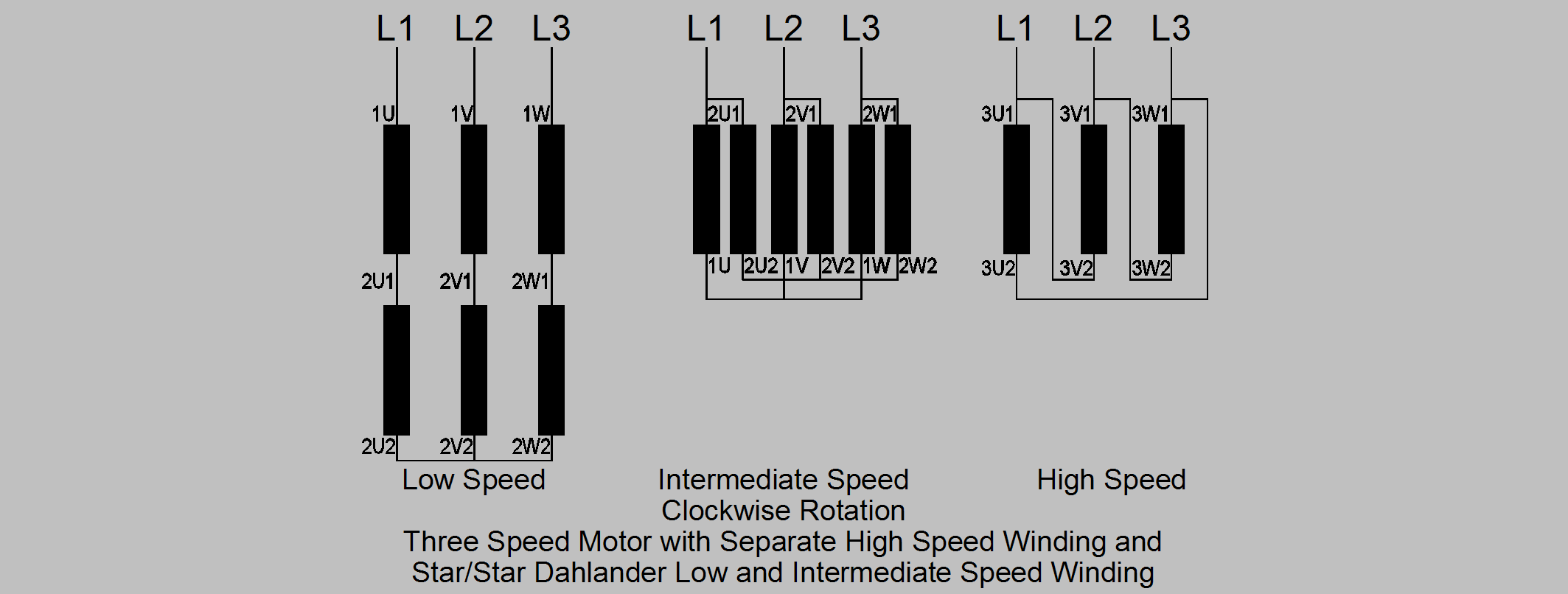
Details of terminal idents for three speed motors with Dahlander star/star windings for low and intermediate speed and a separate winding for high speed (clockwise rotation).
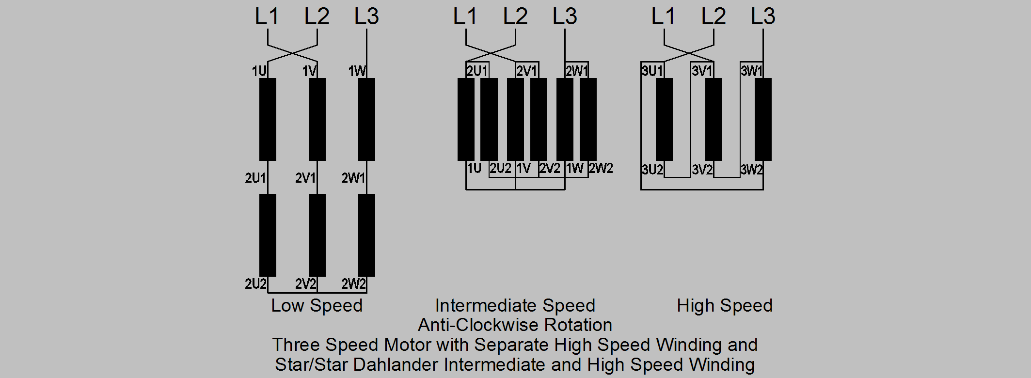
Details of terminal idents for three speed motors with Dahlander star/star windings for low and intermediate speed and a separate winding for high speed (anti-clockwise rotation).
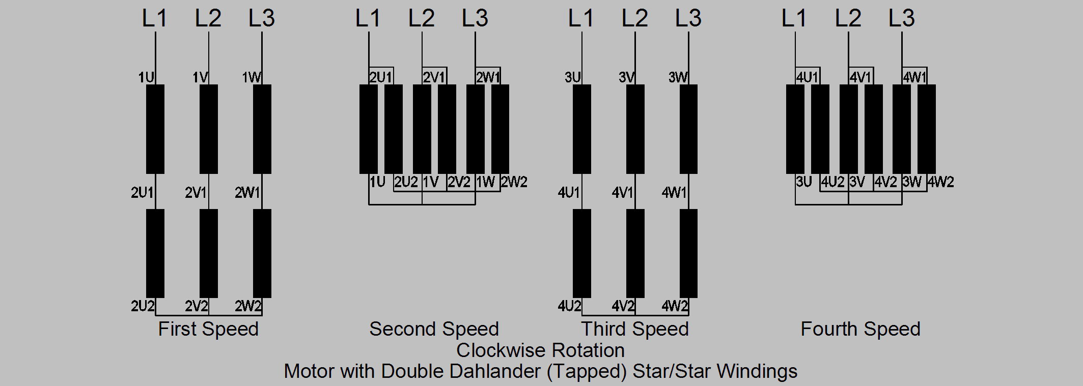
Details of terminal idents for four speed motors with Dahlander star/star windings for first and second speeds and a separate Dahlander star/star winding for third and fourth speeds (clockwise rotation).
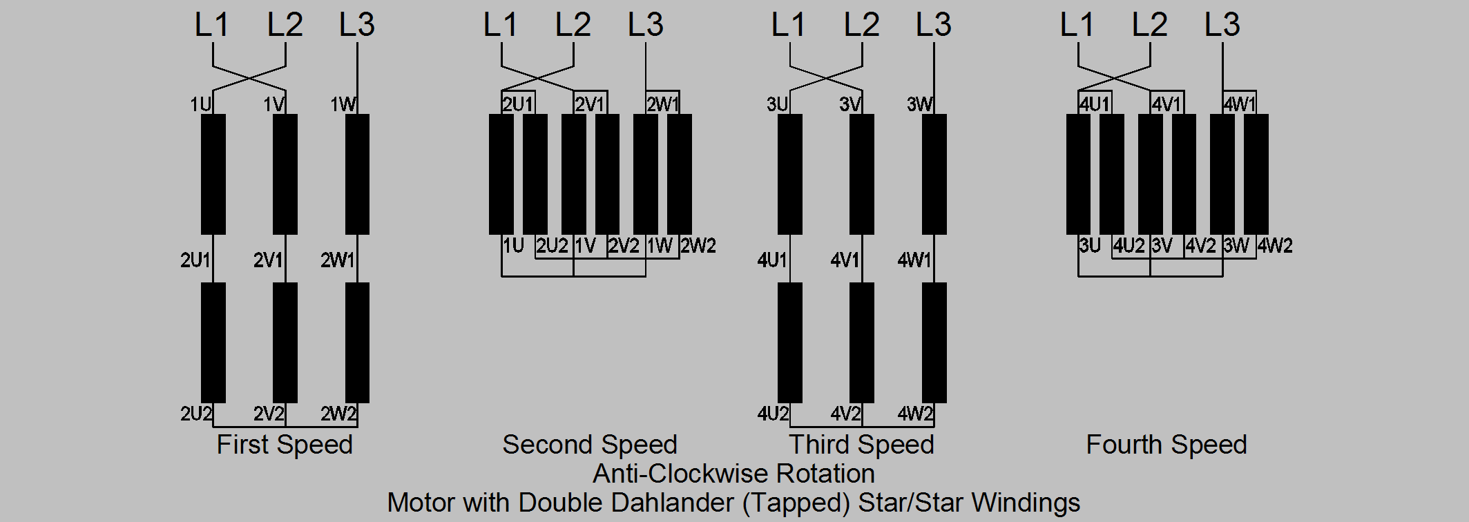
Details of terminal idents for four speed motors with Dahlander star/star windings for first and second speeds and a separate Dahlander star/star winding for third and fourth speeds (anti-clockwise rotation).
Another type of motor is the wound rotor type where the rotor windings are brought out via slip rings.
Details of terminal idents for motors with wound rotors.
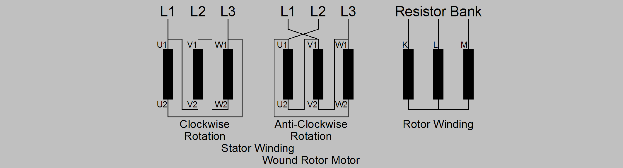
The resistance bank is external to the motor and is designed to control the starting current and torque and will have a number of stages to control the acceleration.